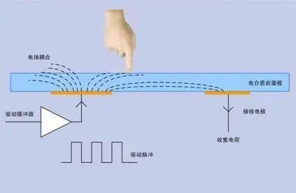
By utilizing the capacitive coupling effect, transparent conductive electrodes are embedded in the screen to form an induced electric field. Human fingers are conductors, and when touched, they generate equivalent capacitance with the screen electrodes, causing changes in local charge/electric field. The touch chip detects the changes and calculates the touch coordinates.
1、 Core structure of capacitive touch screen
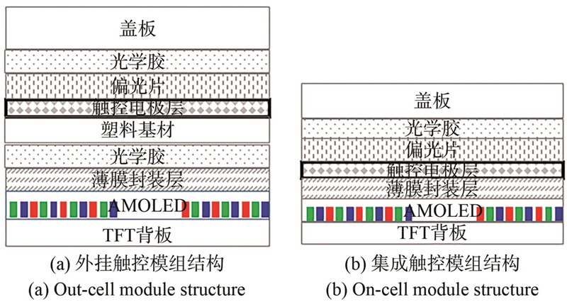
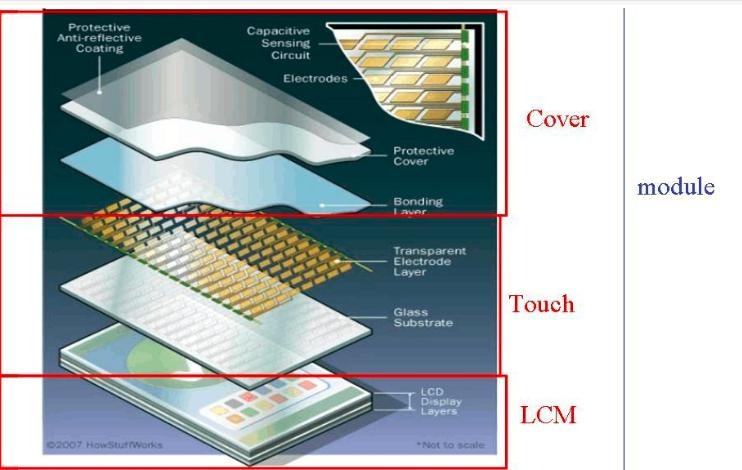
The mainstream projection capacitive screen has a multi-layer stacked structure
a. Cover glass: The outermost layer is made of tempered glass material, mainly used to protect the internal structure of the screen, while ensuring high transparency and not affecting display and touch sensing;
b. ITO sensing layer: The core touch layer is divided into upper and lower layers, with the upper layer being the X-axis driving electrode (Tx) and the lower layer being the Y-axis sensing electrode (Rx). The two electrodes are arranged in a cross pattern to form dense mutual capacitance nodes, and the electrode spacing is usually a few millimeters, directly determining the physical resolution of the screen touch;
c. Shielding layer: located between the ITO sensing layer and the display layer, used to suppress the electromagnetic noise of the display panel itself and external electromagnetic interference, ensuring the stability of touch signals;
d. Display layer: The bottom layer is an LCD/OLED display panel, responsible for image display and working in conjunction with the touch layer to achieve the integrated function of "display+touch".
2、 Working principle of capacitive touch screen
The working principle diagram should highlight the core process of "electric field establishment touch disturbance signal detection"
a. Touchless state: The touch controller applies a high-frequency excitation signal of 100-250 Hz to the X-axis driving electrode (Tx), and the Y-axis sensing electrode (Rx) synchronously induces stable charges. Each mutual capacitance node establishes a reference capacitance C0, and a uniform and stable electrostatic field is formed on the screen surface;
b. Touch triggered state: When the human body, as a conductive body (equivalent to ground), contacts the screen, the fingers form coupling capacitance with the Tx and Rx electrodes at the touch point, causing local electric field disturbance and mutual capacitance value attenuation. The capacitance change satisfies Δ C=Ctouch − C0;
c. Signal detection and positioning: The touch controller captures small capacitance changes at the fF level (10-15F) by scanning the Tx electrode line by line and sampling the Rx electrode signal column by column at high frequency. After signal conditioning, the touch coordinates are calculated using the centroid algorithm and finally reported to the main control chip to complete the touch response.
3、 Self capacitance and mutual capacitance working modes
The schematic diagram of the two working modes needs to clearly distinguish between the electrode connection method and the detection logic
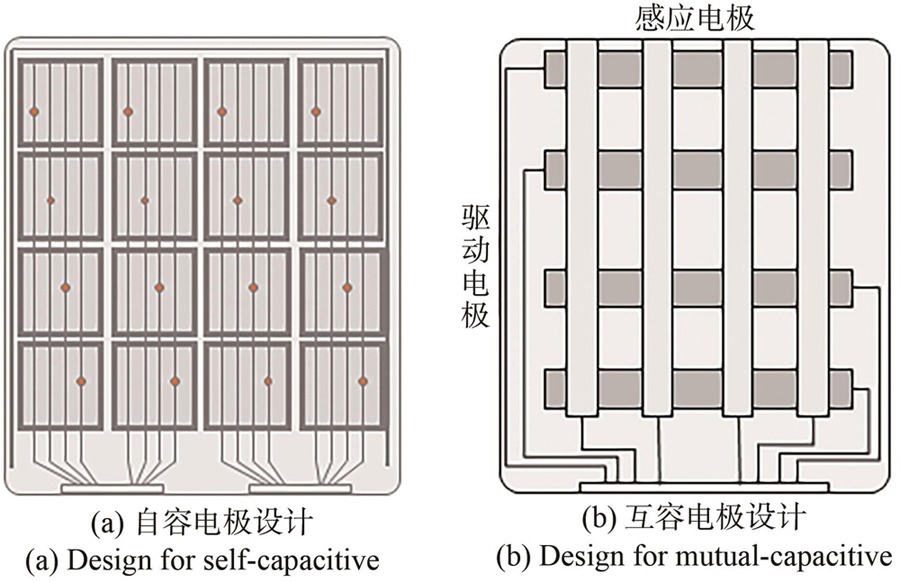
a. Self capacitance mode: A single electrode directly forms a capacitance with respect to the ground, and the change in capacitance of a single electrode with respect to the ground is detected to achieve positioning. The structure is simple, and the schematic diagram can reflect the capacitance circuit of "electrode ground", with the characteristics of "easy crosstalk and single point touch mainly" marked;
b. Mutual capacitance mode (mainstream): The X-axis Tx electrode intersects with the Y-axis Rx electrode, forming a mutual capacitance Cm at the intersection point. The change in mutual capacitance at the intersection point is detected to achieve positioning. The schematic diagram can reflect the structure of the "Tx Rx intersection node", marked with the characteristics of "high precision, multi touch, and strong anti-interference".